Contents
Introduction
A node is a physical element that exists at runtime and represents a computational resource, generally having atleast some memory and, often, processing capability.
We use nodes to model the topology of the hardware on which our system executes. A node typically represents a processor or a device on which components may be deployed.
When we architect a software-intensive system, we have to consider both its logical and physical dimensions. On the logical side, you’ll find things such as classes, interfaces, collaborations, interactions and state machines. On the physical side you’ll find components and nodes.
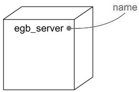
In UML, a node is represented as a cube as shown below. Using stereotypes we can tailor this notation to represent specific kinds of processors and devices.
Nodes and Components
In many ways, nodes are like components: Both have names, both may participate in dependency, generalization and association relationships. Both may be nested, both may have instances, both may be participants in interactions. However, there are significant differences between nodes and components:
- Components are things that participate in the execution of a system. Nodes are things that execute components.
- Components represent the physical packaging of logical elements, nodes represent the physical deployment of components.
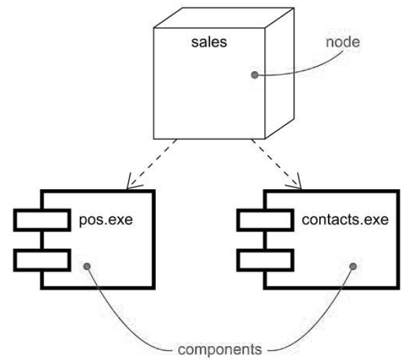
This first difference is the most important. Simply put, nodes execute components; components are things that are executed by nodes.
A set of objects or components that are allocated to a node as a group is called a distribution unit.
Connections
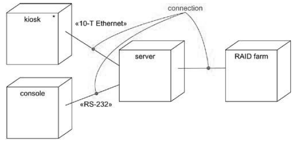
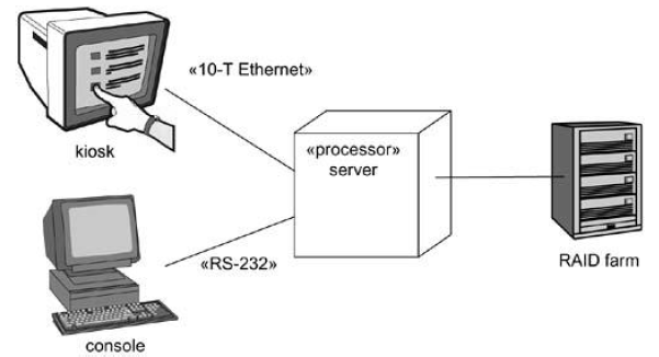
The most common kind of relationship we’ll use among nodes is an association. In this context, an association represents a physical connection among nodes, such as an Ethernet connection, a serial line, or a shared bus as shown below. We can even use associations to model indirect connections, such as a satellite link between distant processors.
Common Modeling Techniques
Modeling processors and devices
To model processors and devices:
- Identify the computational elements of your system’s deployment view and model each as a node.
- If these elements represent generic processors and devices, then stereotype them as such. If they are kinds of processors and devices that are part of the vocabulary of your domain, then specify an appropriate stereotype with an icon for each.
- As with class modeling, consider the attributes and operations that might apply to each node.
Modeling the distribution of components
To model the distribution of components:
- For each significant component in your system, allocate it to a given code.
- Consider duplicate locations for components.
- Render this allocation in one of the three ways:
- Don’t make the allocation visible, but leave it as part of the backplane of your model that is, in each node’s specification.
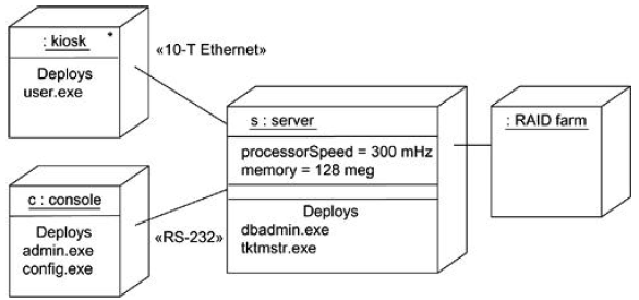
- Using dependency relationships, connect each node with the components it deploys.
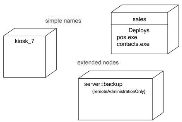
- List the components deployed on a node in an additional compartment.

Suryateja Pericherla, at present is a Research Scholar (full-time Ph.D.) in the Dept. of Computer Science & Systems Engineering at Andhra University, Visakhapatnam. Previously worked as an Associate Professor in the Dept. of CSE at Vishnu Institute of Technology, India.
He has 11+ years of teaching experience and is an individual researcher whose research interests are Cloud Computing, Internet of Things, Computer Security, Network Security and Blockchain.
He is a member of professional societies like IEEE, ACM, CSI and ISCA. He published several research papers which are indexed by SCIE, WoS, Scopus, Springer and others.

Leave a Reply