Contents
Introduction
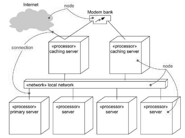
Deployment diagrams are one of the two kinds of diagrams used in modeling the physical aspects of an object-oriented system. A deployment diagram shows the configuration of run time processing nodes and the components that live on them.
We use deployment diagrams to model the static deployment view of a system. A deployment diagram is a diagram that shows the configuration of run time processing nodes and the components that live on them.
Common Properties
A deployment is just a special kind of diagram that shares the same properties as all other diagrams like: a name and graphical contents. What distinguishes a deployment diagram from the rest of the diagrams is its content.
Contents
A deployment diagram commonly contains:
- Nodes
- Dependency and association relationships
Like all other diagrams, deployment diagrams may contain notes and constraints.
Deployment diagrams may also contain components, each of which must live on some node. Deployment diagrams may also contain packages and subsystems.
Common Uses
When modeling the static deployment view of a system, we’ll typically use deployment diagrams in one of the three ways:
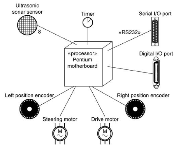
- To model embedded systems.
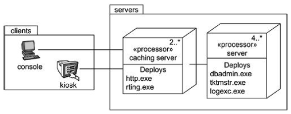
- To model client/server systems.
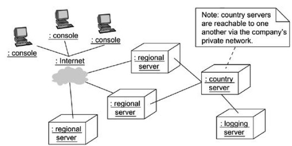
- To model fully distributed systems.
Common Modeling Techniques
Modeling an embedded system
To model an embedded system:
- Identify the devices and nodes that are unique to your system.
- Provide visual cues, especially for unusual devices, by using stereotypes.
- Model the relationships among these processors and devices in a deployment diagram. Similarly, specify the relationship between components and nodes.
- As necessary, expand on the intelligent devices by modeling their structure with a more detailed deployment diagram.
Modeling a client/server system
To model a client/server system:
- Identify the nodes that represent your system’s client and server processors.
- Highlight those devices that are relevant to the behavior of your system.
- Provide visual cues for these processors and devices via stereotyping.
- Model the topology of these nodes in a deployment diagram.
Modeling a fully distributed system
To model a fully distributed system:
- Identify the system’s devices and processors as for simpler client/server systems.
- If you need to reason about the performance of the system’s network or the impact of changes to the network, be sure to model these communication devices to the level of detail sufficient to make assessments.
- Pay close attention to logical groupings of nodes, which you can specify by using packages.
- Model these devices and processors using deployment diagrams.
- If you need to focus on the dynamics of the system, introduce use case diagrams to specify the kind of behavior you are interested in, and expand on these use cases with interaction diagrams.

Suryateja Pericherla, at present is a Research Scholar (full-time Ph.D.) in the Dept. of Computer Science & Systems Engineering at Andhra University, Visakhapatnam. Previously worked as an Associate Professor in the Dept. of CSE at Vishnu Institute of Technology, India.
He has 11+ years of teaching experience and is an individual researcher whose research interests are Cloud Computing, Internet of Things, Computer Security, Network Security and Blockchain.
He is a member of professional societies like IEEE, ACM, CSI and ISCA. He published several research papers which are indexed by SCIE, WoS, Scopus, Springer and others.


Thanks Suryateja,
I really appreciate the tutorial.
LKL
Welcome!