Contents
Introduction
Component diagrams are one of the two kinds of diagrams for modeling the physical aspects of object-oriented software systems. A component diagram shows the organization and dependencies among a set of components. We use component diagrams to model the static implementation view of a software system.
Common Properties
A component is just a special kind of a diagram and shares the same common properties as the other diagrams like: a name and graphical contents. What distinguishes a component diagram from the rest of the diagrams is its content.
Content
Component diagram commonly contain:
- Components
- Interfaces
- Dependency, generalization, association and realization relationships.
Like all other diagrams, component diagrams may contain notes and constraints. Component diagrams may also contain packages.
Common Uses
When modeling the static implementation view of a system, we will typically use component diagrams in one of four ways:
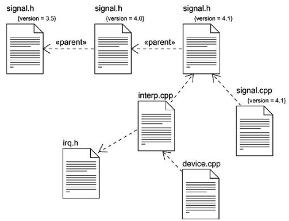
- To model source code.
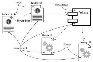
- To model executable releases.
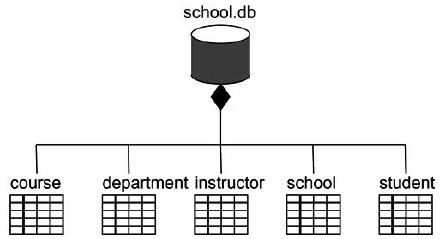
- To model physical databases.
- To model adaptable systems.
Common Modeling Techniques
Modeling source code
To model a system’s source code:
- Either by forward or reverse engineering, identify the set of source code files of interest and model them as components stereotypes as files.
- For larger systems, use packages to show groups of source code files.
- Consider using tagged values indicating such information as the version number of the source code file, its author, and the date it was last changed.
- Model the compilation dependencies among these files using dependencies.
Modeling an executable release
To model an executable release:
- Identify the set of components you’d like to model.
- Consider the stereotype of each component in this set.
- For each component in this set, consider its relationship to its neighbors. Most, often this will involve interfaces that are realized by certain components and then imported by others.
Modeling a physical database
To model a physical database:
- Identify the classes in your model that represent your logical database schema.
- Select a strategy for mapping these classes to tables. You have to also consider the physical distribution of your databases.
- To visualize, specify, construct and document your mapping, create a component diagram that contains components stereotyped as tables.
- Where possible, use tools to help you transform your logical design into a physical design.
Modeling adaptable systems
To model an adaptable system:
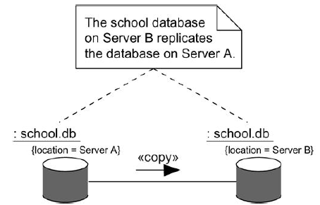
- Consider the physical distribution of the components that may migrate from node to node. We can specify the location of a component instance by marking it with a location tagged value.
- If you want to model the actions that cause a component to migrate, create a corresponding interaction diagram that contains component instances. We can illustrate a change of location by drawing the same instance more than once, but with different values for its location tagged value.

Suryateja Pericherla, at present is a Research Scholar (full-time Ph.D.) in the Dept. of Computer Science & Systems Engineering at Andhra University, Visakhapatnam. Previously worked as an Associate Professor in the Dept. of CSE at Vishnu Institute of Technology, India.
He has 11+ years of teaching experience and is an individual researcher whose research interests are Cloud Computing, Internet of Things, Computer Security, Network Security and Blockchain.
He is a member of professional societies like IEEE, ACM, CSI and ISCA. He published several research papers which are indexed by SCIE, WoS, Scopus, Springer and others.

Leave a Reply