The things in diagrams are connected with one another through relationships. So, relationships are the connections between things. In UML, the four important relationships are dependency, generalization, association and realization. Each type of relationship has its own graphical representation.
If you are familiar with the basics regarding the UML relationships, you can continue reading the rest of the article. Otherwise, first have a look at the basics of relationships in UML.
Now, let’s have a look at the advanced information that can be represented using the above relationships:
Contents
Dependency
The dependency relationship is also known as using relationship i.e., if the specification of one thing (for example Graphics class code) changes then it will automatically affect the behavior of another thing (for example Hello class using the drawstring method of Graphics class) that uses it. A dependency relationship is graphically represented as a dashed arrow.
In general, a plain dependency relationship is reasonable for representing the using relationship between two things. But, if the user needs to specify extra information like the nature of the dependency relationship, he/she can use the predefined stereotypes that can be applied to dependency relationship.
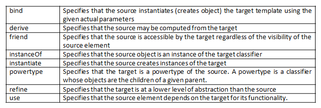
There are about 17 such stereotypes and are organized into 6 groups based on which things are participating in the dependency relationship. The stereotypes are as follows:
First group consists of eight stereotypes that apply to dependency relationship between classes. They are as follows:
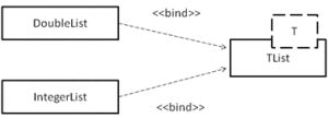
Examples:
<<bind>>
<<derive>>
<<friend>>
<<instanceOf>>
<<instantiate>>
<<powertype>>
<<refine>>
<<use>>
There are two stereotypes that apply to dependencies between packages. They are:
Examples:
<<access>>
<<import>>
Two stereotypes apply to dependency relationship among use case. They are:
Examples:
<<extend>>
<<include>>
Three stereotypes apply to interactions among objects. They are:
Examples:
<<become>>
<<call>>
<<copy>>
One stereotype applies to dependencies in the context of state machines:
One stereotype applies to dependencies in the context of subsystem:
Example:
Generalization
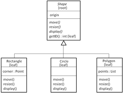
A generalization relationship represents generalization-specialization relationship between classes. The class with the general structure and behavior is known as the parent or superclass and the class with specific structure and behavior is known as the child or subclass. Consider the below class hierarchy:
Shape class is the parent or super class and the remaining three classes namely Rectangle, Circle and Polygon are the child or subclasses of the Shape class.
A subclass in the generalization relationship automatically inherits the state and behavior of the superclass. The generalization relationship is also known as the “is-a” relationship. If a class has only one parent, such inheritance is known as single inheritance and if a class has one or more parents, such inheritance is known as multiple inheritance.
To represent extra semantics in a generalization relationship, UML provides one stereotype and four constraints. The stereotype on generalization relationship is:
There are four standard constraints that apply to the generalization relationship:
Association
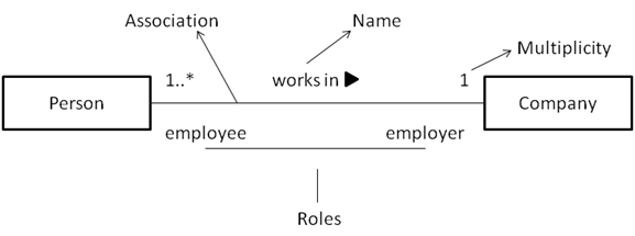
Association is a structural relationship which denotes a connection between two or more things. The association relationship can represent either physical or logical connections between things. The graphical representation of the association relationship is a solid line.
The four basic adornments for an association relationship are: name, role at each end of the association, multiplicity at each end of the association and aggregation. Over these basic features, there are other advanced features like: navigation, visibility, qualification, composition and association classes.
Given an association between two things, we can navigate from one thing to another and vice versa. By default the navigation of an association is bidirectional. In some cases we may need to navigate in only direction. For example, given an order, we can get the details of the products in the order. But, if we consider a product, there might be no need to know about the order to which it belongs.
Visibility
Given an association, we can navigate from one object to another. However, in some situations we may want to limit the visibility (access) of an object to the objects outside the association relationship.
To limit the visibility of an object, we can use the visibility specifiers: public (+), private (-) and protected (#). For example, a usergroup object can access the user object and an user object can access the password. If, private visibility is specified for the password object, the usergroup object cannot access the password of the user object.
Qualification
In binary associations, where two classes are connected together, if one object of a class has to identify a set of instances of another class, we can use qualifiers. A qualifier is a set of attributes of an association which is used to identify a set of instances of a class.
Each qualifier is represented with a name and type in a rectangle box at the qualified end of the association relationship. For example, a bank object is able to recognize the person (account holder) based on the account number. So, account number is the qualifier which is used to identify an account holder.
Composition
The composition is a flavor of association relationship. Composition as well as aggregation relationships represent whole-part relationships, in which one thing is a part of the other thing.
There is a simple difference between the association and composition relationships. In composition, the lifetime of the part is dependent of the lifetime of the whole thing. Where as in aggregation, the lifetime of the part is independent of the whole thing.
Composition is graphically represented by adorning the association relationship with a filled diamond head near the whole end.
Association Class
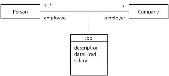
Sometimes in an association relationship, the association might have attributes or properties like a class does. In such cases, it is modeled as an association class. An association class in UML is represented with a class icon attached to the association with a dashed line.
Apart from the above advanced features, UML provides six constraints that can be applied to an association. They are:
Realization
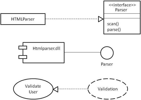
Realization is a semantic relationship between classifiers, where one classifier provides the specification which is implemented by the other classifier. Realization can exist between an interface and class, interface and a component and between a use case and collaboration.
Realization is graphically represented as dashed line with a hollow arrow head pointing towards the classifier which provides the specification.
Common Modeling Techniques
Modeling Webs of Relationships
To model webs of relationships,
- Apply use cases and scenarios to find the relationships between the abstractions in the system.
- Start by modeling the structural relationships (associations) between the things. These specify the structure of the system.
- Then, model the generalization-specialization relationships.
- Finally, after modeling the remaining relationships go for dependency relationships.
- After representing all the relationships, transform their basic representation by applying the advanced features to your intent.

Suryateja Pericherla, at present is a Research Scholar (full-time Ph.D.) in the Dept. of Computer Science & Systems Engineering at Andhra University, Visakhapatnam. Previously worked as an Associate Professor in the Dept. of CSE at Vishnu Institute of Technology, India.
He has 11+ years of teaching experience and is an individual researcher whose research interests are Cloud Computing, Internet of Things, Computer Security, Network Security and Blockchain.
He is a member of professional societies like IEEE, ACM, CSI and ISCA. He published several research papers which are indexed by SCIE, WoS, Scopus, Springer and others.









Hello surya teja,
your content is exceptional ,but while your taking any examples for any concept explain about the diagram also ,so that it is easy us to understand.
thank you.