In this article we will cover how to implement digital input and output using NodeMCU ESP8266. If your are new to Internet of Things (IoT), learn about IoT by visiting our Internet of Things tutorial for beginners.
Watch this video to learn about digital input and output using NodeMCU:
Contents
Aim of Experiment
To implement digital input output
Components Required
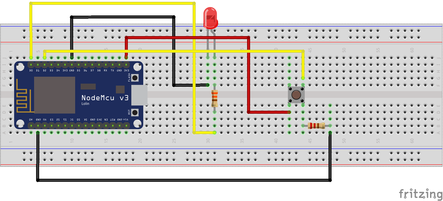
- NodeMCU – 1
- LED – 1
- 330 Ω Resistor – 1
- 10 kΩ Resistor – 1 (acts as a pull down resistor)
- Pushbutton – 1
- Breadboard – 1
Connections Diagram (Schematic)
Code (C++/Arduino IDE)
//By default, NodeMCU built-in LED is connected to pin D4
const int led_pin = D0;
const int push_pin = D2;

void setup() {
  // put your setup code here, to run once:
  pinMode(led_pin, OUTPUT);
  pinMode(push_pin, INPUT);
}

void loop() {
  // put your main code here, to run repeatedly:
  if(digitalRead(push_pin) == 1){
    digitalWrite(led_pin, HIGH);
  }
  else{
    digitalWrite(led_pin, LOW);
  }
}

Suryateja Pericherla, at present is a Research Scholar (full-time Ph.D.) in the Dept. of Computer Science & Systems Engineering at Andhra University, Visakhapatnam. Previously worked as an Associate Professor in the Dept. of CSE at Vishnu Institute of Technology, India.
He has 11+ years of teaching experience and is an individual researcher whose research interests are Cloud Computing, Internet of Things, Computer Security, Network Security and Blockchain.
He is a member of professional societies like IEEE, ACM, CSI and ISCA. He published several research papers which are indexed by SCIE, WoS, Scopus, Springer and others.


Leave a Reply