Contents
Aim
To implement High-Level Data Link Control (HDLC) protocol.
S/W required
Cisco Packet Tracer
Theory
HDLC (High-Level Data Link Control) is a bit-oriented protocol that is used for communication over the point-to-point and multipoint links. This protocol implements the mechanism of ARQ (Automatic Repeat Request). With the help of the HDLC protocol, full-duplex communication is possible.
In order to make the HDLC protocol applicable for various network configurations, there are three types of stations and these are as follows:
- Primary Station: This station mainly looks after data like management. In the case of the communication between the primary and secondary station; it is the responsibility of the primary station to connect and disconnect the data link. The frames issued by the primary station are commonly known as commands.
- Secondary Station: The secondary station operates under the control of the primary station. The Frames issued by the secondary stations are commonly known as responses.
- Combined Station: The combined station acts as both Primary stations as well as Secondary stations. The combined station issues both commands as well as responses.
Transfer modes in HDLC
The HDLC protocol offers two modes of transfer that mainly can be used in different configurations. These are as follows:
- Normal Response Mode (NRM)
- Asynchronous Balance Mode (ABM)
Normal Response Mode (NRM)
In this mode, the configuration of the station is unbalanced. There are one primary station and multiple secondary stations. Where the primary station can send the commands and the secondary station can only respond. This mode is used for both point-to-point as well as multiple-point links.
Asynchronous Balance Mode (ABM)
In this mode, the configuration of the station is balanced. In this mode, the link is point-to-point, and each station can function as a primary and as secondary. Asynchronous Balance mode (ABM) is a commonly used mode today.
HDLC frames
In order to provide the flexibility that is necessary to support all the options possible in the modes and configurations that are just described above. There are three types of frames defined in the HDLC:
- Information Frames (I-frames): These frames are used to transport the user data and the control information that is related to the user data. If the first bit of the control field is 0 then it is identified as I-frame.
- Supervisory Frames (S-frames): These frames are only used to transport the control information. If the first two bits of the control field are 1 and 0 then the frame is identified as S-frame.
- Unnumbered Frames (U-Frames): These frames are mainly reserved for system management. These frames are used for exchanging control information between the communicating devices.
Each type of frame mainly serves as an envelope for the transmission of a different type of message.
Activity
Steps
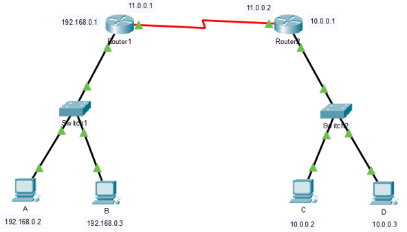
Open Cisco Packet Tracer and create a topology as shown in the below figure. Use PT-Router while creating the routers. The red connection (cable) between the two routers is a Serial DTE cable.
2. Assign IP addresses to the PCs A, B, C, and D as shown in the above figure.
3. Assign Default Gateway IP address for PCs A and B as 192.168.0.1 and 10.0.0.1 for PCs C and D.
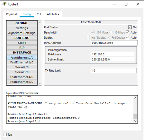
4. Open Router1 and configure its FastEthernet0/0 port as shown in the below figure.
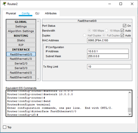
5. Open Router2 and configure its FastEthernet0/0 port as shown in the below figure.
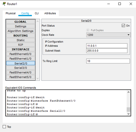
6. Open Router1 and configure its Serial2/0 port as shown in the below figure. Also, make sure that the Clock Rate is as shown in the below figure.
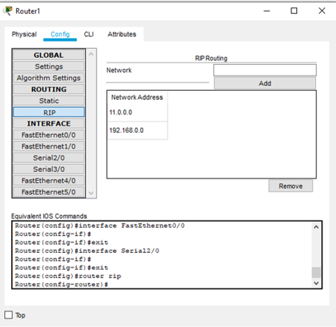
7. Open Router1 and configure the RIP (Routing Information Protocol) settings. Add the networks 11.0.0.0 and 192.168.0.0 as shown in the below figure.
8. Open Router2 and configure its Serial2/0 port as shown in the below figure. Also, make sure that the Clock Rate is as shown in the below figure.
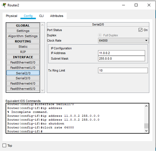
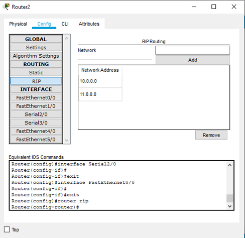
9. Open Router2 and configure the RIP (Routing Information Protocol) settings. Add the networks 11.0.0.0 and 192.168.0.0 as shown in the below figure.
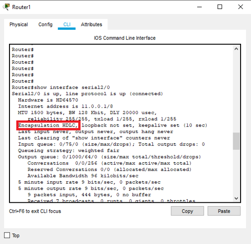
10. By default, the protocol used at data link layer using the serial DTE cable between Router1 and Router2 is HDLC. We can verify it by using the following command in any router’s CLI.
In the result of the above command we see that the encapsulation is already set to HDLC as shown in below figure.
In order to set the encapsulation to HDLC, we need to type the following commands in router’s EXEC mode or privileged mode:
configure terminal
interface serial2/0
encapsulation hdlc
Result
HDLC concepts were understood and simulated successfully using Cisco Packet Tracer.
Visit DCCN lab programs for more study material.

Suryateja Pericherla, at present is a Research Scholar (full-time Ph.D.) in the Dept. of Computer Science & Systems Engineering at Andhra University, Visakhapatnam. Previously worked as an Associate Professor in the Dept. of CSE at Vishnu Institute of Technology, India.
He has 11+ years of teaching experience and is an individual researcher whose research interests are Cloud Computing, Internet of Things, Computer Security, Network Security and Blockchain.
He is a member of professional societies like IEEE, ACM, CSI and ISCA. He published several research papers which are indexed by SCIE, WoS, Scopus, Springer and others.

Leave a Reply