Contents
Aim
To connect two or more PCs or Laptops in a Local Area Network (LAN).
S/W required
CISCO Packet Tracer (CPT)
Background information
Local Area Network (LAN)
Overview
A local area network (LAN) is a collection of devices connected together in one physical location, such as a building, office, or home. A LAN can be small or large, ranging from a home network with one user to an enterprise network with thousands of users and devices in an office or school.
Regardless of size, a LAN’s single defining characteristic is that it connects devices that are in a single, limited area. In contrast, a wide area network (WAN) or metropolitan area network (MAN) covers larger geographic areas. Some WANs and MANs connect many LANs together.
What is a LAN?
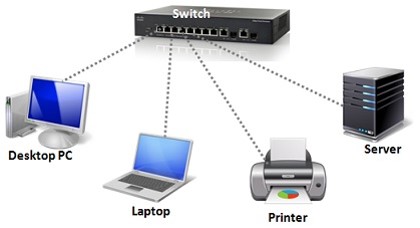
A LAN comprises cables, access points, switches, routers, and other components that enable devices to connect to internal servers, web servers, and other LANs via wide area networks.
The rise of virtualization has also fueled the development of virtual LANs, which enable network administrators to logically group network nodes and partition their networks without a need for major infrastructure changes.
For example, in an office with multiple departments, such as accounting, IT support, and administration, each department’s computers could be logically connected to the same switch but segmented to behave as if they are separate.
What are benefits of a LAN?
The advantages of a LAN are the same as those for any group of devices networked together. The devices can use a single Internet connection, share files with one another, print to shared printers, and be accessed and even controlled by one another.
LANs were developed in the 1960s for use by colleges, universities, and research facilities (such as NASA), primarily to connect computers to other computers. It wasn’t until the development of Ethernet technology (1973, at Xerox PARC), its commercialization (1980), and its standardization (1983) that LANs started to be used widely.
Types of LANs
In general, there are two types of LANs: client/server LANs and peer-to-peer LANs.
A client/server LAN consists of several devices (the clients) connected to a central server. The server manages file storage, application access, device access, and network traffic. A client can be any connected device that runs or accesses applications or the Internet. The clients connect to the server either with cables or through wireless connections.
Typically, suites of applications can be kept on the LAN server. Users can access databases, email, document sharing, printing, and other services through applications running on the LAN server, with read and write access maintained by a network or IT administrator. Most midsize to large business, government, research, and education networks are client/server-based LANs.
A peer-to-peer LAN doesn’t have a central server and cannot handle heavy workloads like a client/server LAN can, and so they’re typically smaller. On a peer-to-peer LAN, each device shares equally in the functioning of the network. The devices share resources and data through wired or wireless connections to a switch or router. Most home networks are peer-to-peer.
Activity 1
Connecting two computers (point-to-point connection) using an Ethernet crossover cable.
Steps
1. Open Cisco Packet Tracer (CPT).
2. Click on “End Devices” and select “PC”. Repeat this to create another “PC”.
3. Click on “Connections” and select “Copper Cross-Over” and connect the two PCs. The network design will be as shown below:
4. Click on the first PC to see the PC controls. Click on “Desktop” tab. Click on “IP Configuration”. Give the IP address value as “192.168.1.10”. Close the window.
5. Repeat the above step for the second PC and assign the IP address as “192.168.1.20”.
6. Enter “Simulation” mode.
7. Click on “Add Simple PDU” and click on one PC as the source and click on another PC to make it the destination.
8. Run the simulation.
Result
Two PCs were connected using a crossover cable and communication between the two PCs was observed.
Activity 2
Creating a star topology using 4 PCs and a hub.
Steps
1. Open CPT.
2. Click on “End Devices” and select “PC”. Repeat this to create another 3 PCs.
3. Click on “Network Devices” and select “Hubs” sub category. Now select “PT-Hub” and place it on the workspace.
4. Name the hub as “Hub” and the 4 PCs as “A”, “B”, “C”, and “D”.
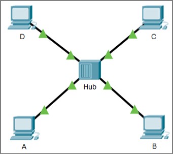
5. Connect the 4 PCs with the hub using a Copper Straight-Through cable. The network design will be as shown below:
6. Now assign IP address to the PCs A, B, C, and D as 192.168.2.2, 192.168.2.3, 192.168.2.4, and 192.168.2.5 respectively.
7. Click on “Add Simple PDU” and click on PC “A” as the source and click on another PC “D” to make it the destination.
8. Run the simulation and observe the behavior of the hub.
Result
4 PCs were connected to a hub using a straight-through cable forming a star topology and communication between the two PCs was observed. Also, behavior of the hub was observed.
Activity 3
Creating a star topology using 4 PCs and a switch.
Steps
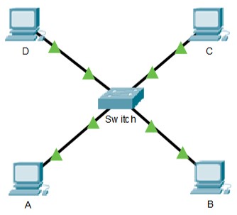
Repeat the steps of the above activity 2. But, instead of a hub use a switch. While selecting a switch, you can select 2960 switch which a well-known and used switch. The network design will look as shown below:
Result
4 PCs were connected to a switch using a straight-through cable forming a star topology and communication between the two PCs was observed. Also, behavior of the switch was observed.
Visit DCCN lab programs for more study material.

Suryateja Pericherla, at present is a Research Scholar (full-time Ph.D.) in the Dept. of Computer Science & Systems Engineering at Andhra University, Visakhapatnam. Previously worked as an Associate Professor in the Dept. of CSE at Vishnu Institute of Technology, India.
He has 11+ years of teaching experience and is an individual researcher whose research interests are Cloud Computing, Internet of Things, Computer Security, Network Security and Blockchain.
He is a member of professional societies like IEEE, ACM, CSI and ISCA. He published several research papers which are indexed by SCIE, WoS, Scopus, Springer and others.


Leave a Reply