Contents
Aim
To configure a network topology using cisco packet tracer.
S/W required
Cisco Packet Tracer
Background information
Overview of a router
A router is a device that connects two or more packet-switched networks or subnetworks. It serves two primary functions: managing traffic between these networks by forwarding data packets to their intended IP addresses, and allowing multiple devices to use the same Internet connection.
There are several types of routers, but most routers pass data between LANs (local area networks) and WANs (wide area networks). A LAN is a group of connected devices restricted to a specific geographic area. A LAN usually requires a single router.
In order to direct packets effectively, a router uses an internal routing table — a list of paths to various network destinations. The router reads a packet’s header to determine where it is going, then consults the routing table to figure out the most efficient path to that destination. It then forwards the packet to the next network in the path.
Activity
Steps
1. Open Cisco Packet Tracer.
2. Create a LAN containing a switch (2960) and 3 PCs. Name the PCs as A, B, and C.
3. Assign IP addresses to PCs created in the above step as 10.0.1.2, 10.0.1.3, and 10.0.1.4.
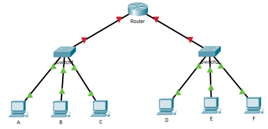
4. Connect all the 3 PCs to the switch.
5. Create another LAN containing a switch and 3 PCs. Name the PCs as D, E, and F.
6. Assign IP addresses to PCs created in the above step as 192.168.1.2, 192.168.1.3, and 192.168.1.4.
7. Connect all the 3 PCs to the switch.
8. Create a router (2901).
9. Connect both the switches to the router. Take care that while connecting the switches to the router, GigabitEthernet ports are selected. The network design looks as shown below:
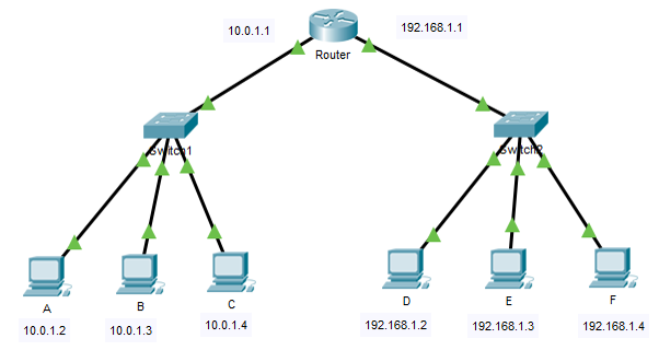
10. Now, we have to configure the router interfaces. Click on router to open the options. Click on “Config”. Click on GigabitEthernet0/0 interface on the left-hand side. Give the IP address as 10.0.1.1 and change (click) the “Port Status” as “On”.
11. Repeat the above step for GigabitEthernet0/1 with IP address as 192.168.1.1.
12. For PCs A, B, and C change the “Default Gateway” in “IP Configuration” to 10.0.1.1.
13. For PCs D, E, and F change the “Default Gateway” in “IP Configuration” to 192.168.1.1. Final network design will be as shown below:
Go to simulation mode and add a PDU from the source as PC A and the destination as PC F. Click on play and watch the data flow.
Result
Two LANs were connected using a router and the topology has been tested.
Visit DCCN lab programs for more study material.

Suryateja Pericherla, at present is a Research Scholar (full-time Ph.D.) in the Dept. of Computer Science & Systems Engineering at Andhra University, Visakhapatnam. Previously worked as an Associate Professor in the Dept. of CSE at Vishnu Institute of Technology, India.
He has 11+ years of teaching experience and is an individual researcher whose research interests are Cloud Computing, Internet of Things, Computer Security, Network Security and Blockchain.
He is a member of professional societies like IEEE, ACM, CSI and ISCA. He published several research papers which are indexed by SCIE, WoS, Scopus, Springer and others.


Leave a Reply