In this article we will look at AT89S8253 Microcontroller. We will learn about its architecture and pin diagram.
Introduction to AT89S8253 Microcontroller
AT89S8253 is a microcontroller manufactured by Atmel. It is widely used, cheap and uses flash memory for storing programs. Makes it ideal for experimentation due to the fact that program can be loaded and erased from it for many times. Besides, thanks to the built-in SPI System (Serial Programing Interface), the program can be loaded to the microcontroller even after embedding the chip in the target device.
Watch this short video on AT89S8253 microcontroller
Some of the features or characteristics of AT89S8253 microcontroller are:
- Compatible with MCS 51 Products
- 12K Bytes of In-System Programmable (ISP) Flash Program Memory
- 2K Bytes EEPROM Data Memory
- 7V to 5.5V Operating Range
- 256 bytes Internal RAM
- 32 Programmable I/O Lines
- Three 16-bit Timer/Counters
- Nine Interrupt Sources
- Programmable Watchdog Timer
- 42-pin PDIP Package Option for Reduced EMC Emission
The internal architecture of AT89S8253 microcontroller is as shown in the below figure.
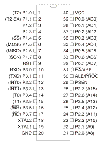
AT89S8253 microcontroller’s pin diagram is as shown in the below figure.
Vcc
- Power supply voltage (4-6V)
GND
- Ground ( Negative supply pole)
Port 0 (P0.0-P0.7)
- If configured as outputs, each of these pins can be connected to up to 8 TTL inputs
- If configured as inputs, the pins can be used as high-impedance inputs as their potential is not defined relative to ground, i.e. they are floating
Port 1 (P1.0-P1.7)
- If configured as outputs, each of these pins can be connected to up to 4 TTL inputs
- When configured as inputs, these pins act as standard TTL inputs, that is, each of them is internally connected to the positive supply voltage via a resistor of relatively high impedance
Port 2 (P2.0-P2.7)
- Whether configured as an input or an output, this port acts the same as Port 1
- If external memory is used, the high byte of the address (A8-A15) comes out on the Port 2 which is thus used for addressing it
Port 3 (P3.0-P3.7)
- Similar to P1, Port 3 pins can be used as general inputs or outputs
RST
- Logic one (1) on this pin causes the microcontroller to be reset
ALE/PROG
- In normal operation, the ALE pin is activated at a constant rate of 1/16 the oscillator frequency and can be used for external clocking and timing purposes
PSEN
- This pin provides a signal used for accessing external program memory (ROM)
EA/VPP
- When this pin is connected to ground, the microcontroller reads program instructions from external program memory
- If internal program memory is used, which is the common case, this pin should be connected to the positive power supply voltage (Vcc)
XTAL 1
- This is internal oscillator input
- It is used for the purpose of synchronizing the operation of the microcontroller with some other circuit or for connecting external oscillator when used
XTAL 2
- This pin is connected to internal oscillator output

Suryateja Pericherla, at present is a Research Scholar (full-time Ph.D.) in the Dept. of Computer Science & Systems Engineering at Andhra University, Visakhapatnam. Previously worked as an Associate Professor in the Dept. of CSE at Vishnu Institute of Technology, India.
He has 11+ years of teaching experience and is an individual researcher whose research interests are Cloud Computing, Internet of Things, Computer Security, Network Security and Blockchain.
He is a member of professional societies like IEEE, ACM, CSI and ISCA. He published several research papers which are indexed by SCIE, WoS, Scopus, Springer and others.


Leave a Reply