In this article we will learn to implement analog input and output using NodeMCU ESP8266. If your are new to Internet of Things (IoT), learn about IoT by visiting our Internet of Things tutorial for beginners.
Contents
Aim of Experiment
To implement analog input output.
Components Required
- NodeMCU – 1
- 100 kΩ Potentiometer – 1
- LED – 1
- 330 Ω Resistor – 1
- Breadboard – 1
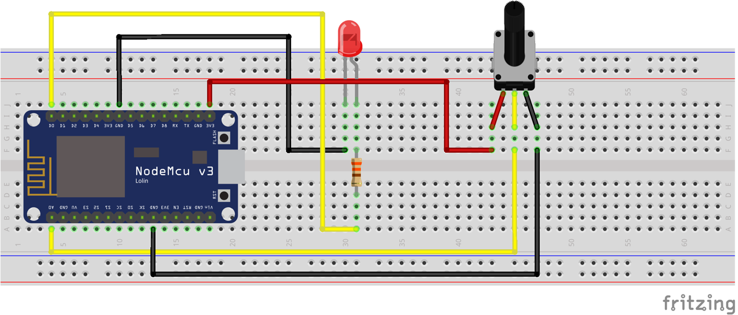
Connections Diagram (Schematic)
Code (C++/Arduino IDE)
// Pins
const int pot_pin = A0;
const int led_pin = D0;

void setup() {
  pinMode(led_pin, OUTPUT);
  pinMode(pot_pin, INPUT);
}

void loop() {

  // Read knob value (0 - 1023)
  int val = analogRead(pot_pin);

  // Convert knob value to PWM value (0 - 255)
  int brightness = map(val, 0, 1023, 0, 255);

  // Set LED brightness
  analogWrite(led_pin, brightness);
}
Video Explanation

Suryateja Pericherla, at present is a Research Scholar (full-time Ph.D.) in the Dept. of Computer Science & Systems Engineering at Andhra University, Visakhapatnam. Previously worked as an Associate Professor in the Dept. of CSE at Vishnu Institute of Technology, India.
He has 11+ years of teaching experience and is an individual researcher whose research interests are Cloud Computing, Internet of Things, Computer Security, Network Security and Blockchain.
He is a member of professional societies like IEEE, ACM, CSI and ISCA. He published several research papers which are indexed by SCIE, WoS, Scopus, Springer and others.


Leave a Reply